J-Walk Gait Trainer | In the News | Design Instructions | Alternative Customizations | Engineering Drawings | Downloads
Engineering Drawings
The following engineering drawings are what were used to construct the original J-Walk’s custom components. These engineering drawings are referenced in Tab 2, and instructions on how to modify these drawings to make modifications as well as how to make a one-for-one recreation of the original J-Walk.
Full size versions of these drawings can be downloaded by right-clicking and saving the attached images or downloading the full PDF of engineering drawings in the Downloads section.
A.1 Engineering Drawings for Existing Components
A.1.1 Left Adjustment Bar

A.1.2 Right Adjustment Bar

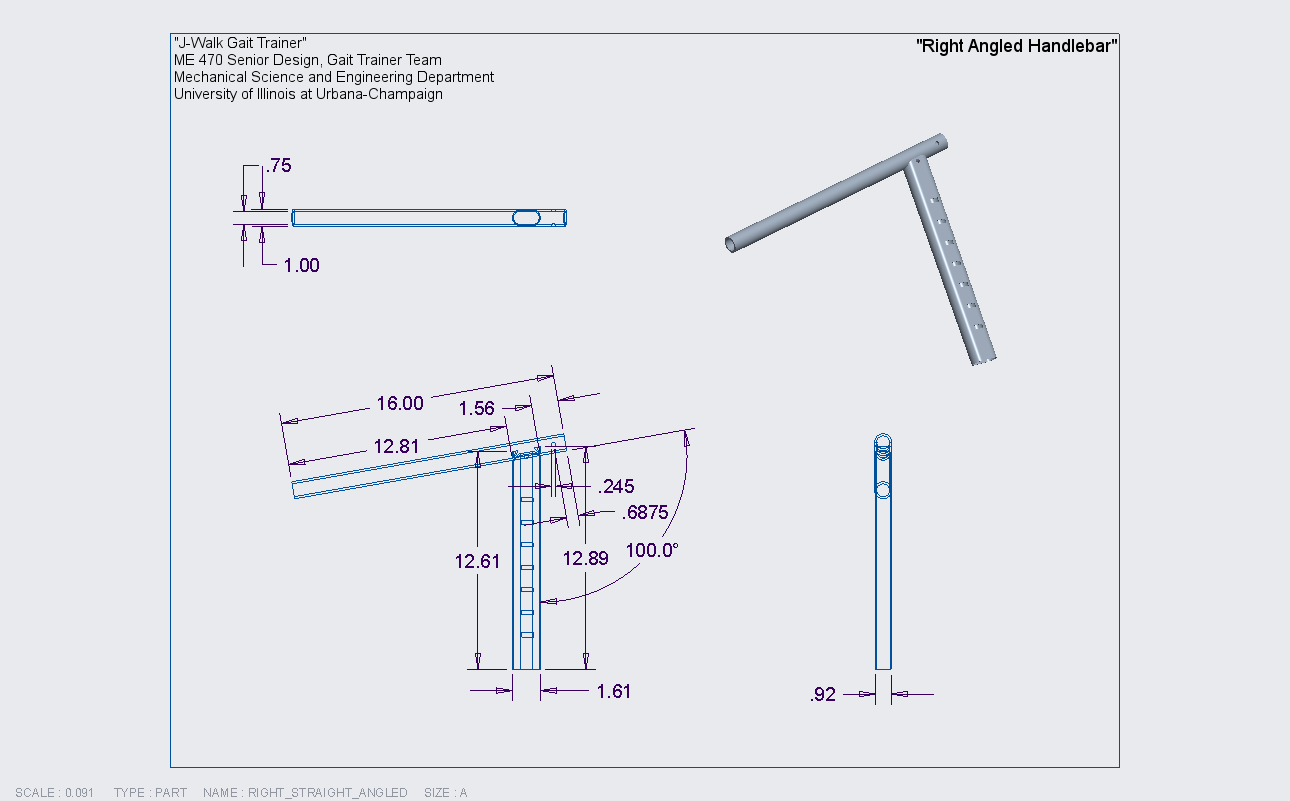
A.2 Engineering Drawings for Handlebars
A.2.1 Left Straight Handlebar

A.2.2 Right Straight Handlebar

A.2.3 Left Angled Handlebar

A.2.4 Right Angled Handlebar
A.3 Engineering Drawings for Frame Extension
A.3.1 Modified Body Frame Tubing

A.3.2 Frame Extension Block

A.3.3 Extension Frame Tubing
