J-Walk Gait Trainer | In the News | Design Instructions | Alternative Customizations | Engineering Drawings | Downloads
Design Instructions
Order Triumph Escape Walker
Customize design
- Choose seat height: Walker comes in 3 sizes:
-
- Super Low – seat height 19”; handle height range 28” – 36”
- Low – seat height 21”; handle height range 29.5” – 37.5”
- Standard – seat height 24”; handle height range 32” – 40”
- Determine handlebar height: To determine the handlebar height, measure the distance from the floor to the crease of your wrist when your arms are fully extended. The top of the handlebars should lie at that height. Further details on this process can be found in the section pertaining to handlebar height.
Find more information about purchasing an Escape Walker from Triumph at their website: https://triumphmobility.com/products/walkers/escape/
Determine Design Specifications
Determine handlebar length
Consult the figure below to determine the maximum length the handlebars can be based on the user’s weight. Be sure your metrics remain under the blue line.
The actual handlebar length can be determined based on the user’s optimal hand placement, as long as the length does not exceed the maximum length determined from Figure 1 above. Note that this length represents the length from the center of the adjustment bar to the end, not the total length.
If the user doesn’t like holding the device at the edge of the handlebars, consider making the handlebar a few inches longer than the distance of the user’s comfortable hand placement. When doing safety calculations, this extra length does not need to be factored in.
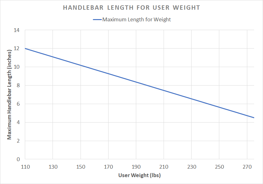
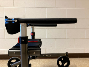
Choose handlebar angle
Two types of handlebars were developed: perpendicular and 10-degree incline. The Inclined handlebars may help to reduce pressure on the wrists [1], but can create a discrepancy between your walking hand placement and your sitting elbow placement. The options are shown in Figure 2 and Figure 3. You may also consider creating handles with a smaller angle.
Determine the proper height of the handlebars
A measurement should be taken to determine the height from the ground to the user’s wrist crease. Ensure that when taking this measurement, the user is supported in the way that they intend the J-Walk to support them in, i.e. do not take this measurement with the user in a slouched over, non-supported position, as this will result in the device having an improper handlebar height for the user. Taken correctly, this measurement will allow for proper height placement of the handlebars [2].
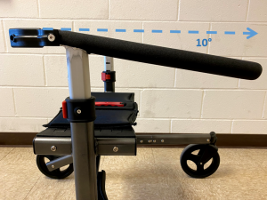
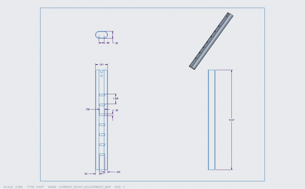
Using this measurement, you will need to determine what the intended notch position that the custom handlebars are meant to be used at, as this will allow you determine how the new handlebars will need to be fabricated. Note that each handlebar notch position is separated by 1.305”, as seen in Figure 4. This step will vary between different cases, as wrist crease height measurements will be different for every person. This will change the intended notch position that will be utilized, and thus one step in the fabrication of the handlebars will be altered from the original plans, however this change should be minor.
In the case of our client, her wrist crease height measurement was 26”. From here, the team determined the proper notch position for the new handlebars by measuring the height of the adjustment bar at different heights, as seen in Table 1. The first usable position for a 26” height for the new handlebar system was determined to be notch position 3, at a total height of 26.25” from the ground to the top of the adjustment bar. The new handlebars were made out of 1 inch diameter aluminum round tubing, so the radius of the tubing (0.5”) also needed to be taken into account for the height adjustment, as this would affect the height of the handlebars when fabricated together with the existing adjustment bar.
Table 1. Total height of the adjustment bar in various notch positions
| Notch Position of Adjustment Bar | Height From Ground to Top of Adjustment Bar [inches] |
|---|---|
| 1 | 23.640 |
| 2 | 24.945 |
| 3 | 26.250 |
| 4 | 27.555 |
| 5 | 28.860 |
| 6 | 30.165 |
| 7 | 31.470 |
From there, it was determined that the height of the adjustment bar component itself would need to be lowered by 0.75” overall, as this would take the overall height of the adjustment bars in the third notch position from 26.25” down to 25.5”. You can see the original height of the adjustment bars (13.07”) in Figure 5 and the modified height of the adjustment bars in the new handlebar system (12.32”) in Figure 6. When the new handlebar tubing is attached to these adjustment bars, the tubing would add 0.5” to this height (due to the existing adjustment bar meeting the round tubing at its centerline, as seen in Figure 7. This will be explained in more detail in the “Assembly Procedure” section). This sets the new handlebar system at a height of 26” when used in notch position 3.
This same process will need to be repeated using your own wrist height measurement, although the heights at each notch position will vary depending on which model of the Triumph Escape that was chosen for modification. This is due to the fact that each model not only has different seat heights, but also different adjustment bar heights at each notch position due to differing base positions. If using the same walker model as the original J-Walk (“Super Low”: 19” seat height), you can reference the table above, but you should also take these measurements on your own as well to ensure that you choose the correct notch position.
If you choose to replicate our design without any modifications, each notch position will correlate to the total handlebar heights as seen in Table 2.
Table 2. Total height of the original design for the new handlebar system in various notch positions
| Notch Position of Adjustment Bar | Height From Ground to Top of New Handlebar System [inches] |
|---|---|
| 1 | 23.390 |
| 2 | 24.695 |
| 3 | 26.000 |
| 4 | 27.305 |
| 5 | 28.610 |
| 6 | 29.915 |
| 7 | 31.220 |
Determine length of bottom frame extension
Use the following equations and diagram to determine the distance that the wheels must extend past the handlebars in order to prevent the gait trainer from tipping.
Consider the worst case scenario – full body weight pushing down on the handlebar and a force pulling the gait trainer forward that is roughly 20% of the user’s body weight. This scenario was modeled into a FBD, seen in Figure 8.
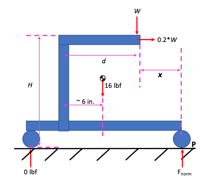
W is the weight of the user, and d is the distance of the hands from the center of the seat. H is the height of the top of the handlebars from the ground (the same distance from the ground to the user’s wrist). Fnorm is the force from the ground on the front wheel. The force on the back wheel is 0 lbf since we are looking at the walker when the back wheel is just barely off the ground (tipping). The location of the walker’s center of gravity was estimated to be 6 in. from the back wheel.
The following equation is used to calculate the moment about point P (the front wheel):
M_P = (16 lbf)*((d + x) – 6 in) + W*x – 0.2*W*H = 0
The following example shown below in Figure 9 is for a user with a body weight of 175 lbs. and a hand placement 13.5 in. from the center of the seat.
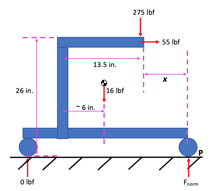
Use the equation above for the example case. The distance from the comfortable hand placement on the handlebars to the wheel was calculated as follows:
M_P = (16 lbf)*((13.5 in + x) – 6 in) + (275 lbf)*x – (55 lbf)*(26 in) = 0
x = 4.5 in.
Since the handlebar needs to be 13.5 in. from the center of the seat, the length of the bottom frame from the center of the seat must be 18 in.
Length of bottom frame = d + x
Length of bottom frame = 13.5 in. + 4.5 in. = 18 in.
In the original Triumph Escape Walker, the front wheel is 6.5 inches from the center of the seat. To make that distance 18 in., an extension piece of 11.5 in. must be attached to the original walker.
Extension = length of bottom frame – 6.5 in.
Extension = 18 in. – 6.5 in. = 11.5 in.
*Please note that, in the plans presented, the extension used is only 11 in. due to size limitations of the available extension tubing. The team deemed this length safe despite the 0.5 in. difference from the calculation due to the approximate nature of the above equations.
Consider your step size
The crossbeams under the seat combined with the limit on handlebar length yield a small area for walking. If your usual step length is 16 inches or greater, you may want to consider a different design, or a different base walker without crossbeams. Adding cushion to the crossbeams may help small interferences. If you plan on designing this for a larger step size, please contact the J-Walk design team.
Assembly Procedure
Order the necessary materials
The following materials are necessary to construct the J-Walk. All the necessary items, each item’s cost, and how to purchase each item are included in Table 3 and Table 4 respectively.. The total of $838.82 is based on the team’s own project budget, however this does not account for shipping and handling for the McMaster-Carr items. Additionally, the overall cost of the project could be lowered to $688.82 ($150 less) if the Triumph Escape is bought directly from Triumph Escape themselves ($200) rather than from an American retailer ($350+). The estimates for the machine shop labor could also be less or more than the stated cost, as these were based on the team’s own experiences. Your experiences may vary.
This budget does not account for the cost of the flared out wheels from the Lifestyle 950 Commando or for the eight extra “screw and nut” sets required for assembly of the frame extension, as you will need to contact Lifestyle Mobility Aids (for the wheels or the screws and nuts) or Triumph Mobility (for the screws and nuts) to find an authorized dealer near you. The cost of the flared wheels and screws and nuts replacements will most likely not exceed more than $40.
Table 3. Projected Open Source Project Cost
| Item | Quantity | Price/Unit | Item Total |
|---|---|---|---|
| Triumph Escape Rollator | 1 | $350 | $350 |
| Triumph Escape Side Frame – Part #37 OR #38
(For Frame Extension) |
2 | $40 | $80 |
| Triumph Escape Frame Screw & Nut – Part #11
(For Frame Extension) |
8 | – | – |
| Lifestyle 950 Commando Flared Out Front Wheel Set | 1 | – | – |
| 6061-T6511 Aluminum Block, 1” width x 1” thickness x 1’ length
(For Frame Extension) (Shipping and tax not included) |
1 | $8.29 | $8.29 |
| 6061-T6 Aluminum Tubing, 1” outer diameter x 0.125” wall thickness x 3’ length
(For Handlebars) (Shipping and tax not included) |
1 | $21.09 | $21.09 |
| 16” Rubber Handlebar Covers | 2 | $17.27 | $34.54 |
| Machine Shop Labor
(Estimate) |
5 | $59 | $295 |
| Welding
(For Handlebars) (Estimate) |
1 | $40 | $40 |
| Foam Edge Protectors
(For Crossbeams) |
1 | $9.90 | $9.90 |
| GRAND TOTAL | $838.82 | ||
Table 4. Links to purchase each item
| Item | Quantity | Link to Purchase |
|---|---|---|
| Triumph Escape Rollator
(In preferred configuration: “Super Low”, “Low”, or “Standard”) (Provided link is for the “Standard” model, however the other two can also be ordered on the same site) |
1 | https://www.amazon.com/dp/B014G8ORPA
OR Call Triumph Mobility at 1.855.546.0711 |
| Triumph Escape Side Frame – Part #37 OR #38
(For Frame Extension) |
2 | Call Triumph Mobility at
1.855.546.0711 |
| Triumph Escape Frame Screw & Nut – Part #11
(For Frame Extension) |
8 | Call Triumph Mobility at
1.855.546.0711 OR Call Lifestyle Mobility Aids at 1.877.843.6464 |
| Lifestyle 950 Commando Flared Out Front Wheel Set | 1 | Call Lifestyle Mobility Aids at
1.877.843.6464 |
| 6061-T6511 Aluminum Block, 1” width x 1” thickness x 1’ length
(For Frame Extension) |
1 | https://www.mcmaster.com/9008k14-9008K141 |
| 6061-T6 Aluminum Tubing, 1” outer diameter x 0.125” wall thickness x 3’ length
(For Handlebars) |
1 | https://www.mcmaster.com/9056k36-9056K363 |
| 16” Rubber Handlebar Covers | 2 | Link on Exercise Equipment Parts website |
| Machine Shop Labor
(Estimate) |
5 | Consult your local machine shop |
| Welding
(For Handlebars) (Estimate) |
1 | Consult your local welding shop |
| Foam Edge Protectors
(For Crossbeams) |
1 | https://www.amazon.com/dp/B01AAAQ2P6 |
Altering the Triumph Escape’s features
- Remove the brakes:
-
- Disassemble the brake system at the back wheels
- Cut the brake wires
- Pull out the remaining wires from the frame
- Rotate the seat (2 people suggested):
-
- Unscrew the four pins holding up the seat
- Unscrew the two pins holding the crossbeams to the frame
- Flip entire assembly and re-attach
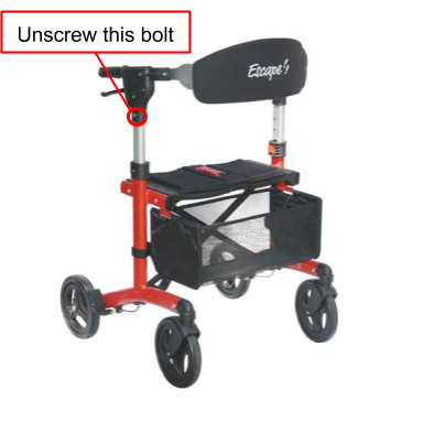
- Disassemble current handlebars:
-
- Unscrew the bolt attaching the adjustment bar to the handlebar casing. You will need an allen key to unscrew this bolt. The bolt you want to unscrew is the one at the very bottom of the plastic handlebar casing, as seen in Figure 10.
- Once this is done, you can separate the adjustment bar from the plastic casing. This will require some force. If there is no one else to help you separate these components, it is easiest to do this by holding the handlebar between your feet and pulling upwards on the metal adjustment bar.
Constructing a set of STRAIGHT handlebars
The following materials will be required to fabricate the new handlebar system. More details can be found on where to purchase these items in the Bill of Materials.
- Round aluminum tubing
- 1” outer diameter, 0.125” wall thickness
- Necessary length depends on the handlebar length determined earlier, however 3’ of tubing should be sufficient for most cases.
- x2 Adjustment bars
- Existing component, taken from the Triumph Escape, as seen in Figure 11.
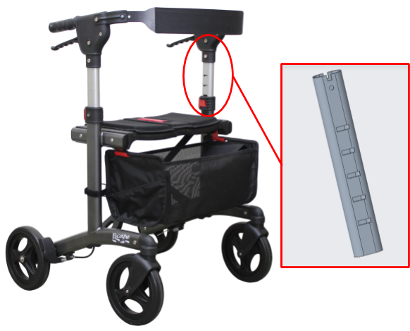
FIGURE 11. The existing adjustment bar component from the Triumph Escape.
- Existing component, taken from the Triumph Escape, as seen in Figure 11.
- x2 16” Rubber handlebar grips
- x2 Backrest attachments
- Existing component, taken from the Triumph Escape, as seen in Figure 12.

Figure 12. The existing backrest attachment component from the Triumph Escape. - Retain the sleeved bolts that were used to attach the backrest attachments to the plastic handle casing, as these will be used for the new handlebar system as well.
- Existing component, taken from the Triumph Escape, as seen in Figure 12.
Consult a local machine shop or welder to make the handlebars as follows:
- Based on the necessary handlebar height determined earlier, modify the existing adjustment bar component.
- Based on however much the total height of adjustment bar needs to be lowered in its intended notch position to get the new handlebar system to the proper height, translate this measurement to the adjustment bar component itself.
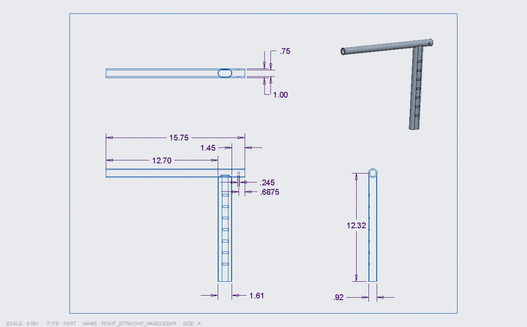
- If modifying the height of the adjustment bar modification, note that the dimension that will be modified is the 12.32” dimension, seen in Figure 13 below (from the engineering drawing for “Straight Left/Right Handlebar”).
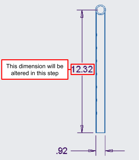
Figure 13. A close-up of the straight handlebar engineering drawing, showing the modified height of the adjustment bar. - The 12.32” dimension correlates to cutting down the previously 13.07” tall adjustment bar (as seen in Figure 14) by 0.75”.
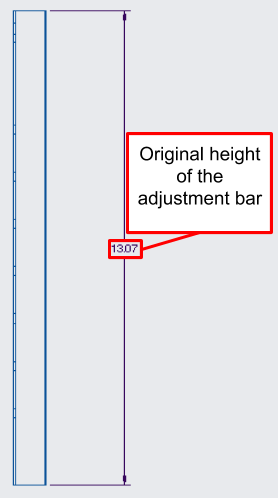
Figure 14. A close-up of the adjustment bar engineering drawing, showing the original height of the component before modification. - Based on how much the height will need to be lowered in your intended notch position (as detailed earlier), the 12.32” dimension will be modified.
- Example:
- The 12.32” dimension indicates how much height to remove from the from the top of the 13.07” tall adjustment bar. (13.07” – 12.32” = 0.75” removal from the existing adjustment bar)
- If the height of the adjustment bar needs to be lowered by 1” instead of 0.75”, the adjustment bar height will be cut down from 13.07” to 12.07”
- This means that the 12.32” dimension as seen above in Figure 13 will now become 12.07”.
- Cut the handlebar tubing to the necessary lengths based on the engineering drawings for the straight handlebars and your necessary handlebar length that was determined earlier.
- If modifying the length of the handlebars, note that the dimension that will be modified is the 12.70” dimension, seen in Figure 15 below (from the engineering drawing for “Straight Left/Right Handlebar”). This figure represents a handlebar length of 13.50”, measured from the vertical centerline of the adjustment bar. Here it is represented as 12.70”, measured from the side of the adjustment bar, as this way of dimensioning the measurement is more useful for fabrication than a dimension represented from an imaginary centerline.
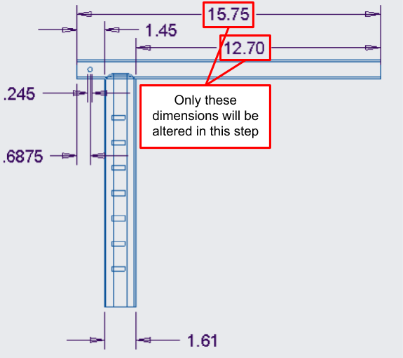
Figure 15. A close-up of the straight handlebar engineering drawing, showing the handlebar length dimensions that will be altered. - Depending on how long your necessary handlebar length is, you will add or subtract from the 12.70” dimension, and the 15.75” dimension will change accordingly as well.
- Example:
- If the necessary handlebar length is 7.00”, then it is 6.50” shorter than the original design’s 13.50” handlebar length. Thus you will subtract 6.50” from the 12.70” dimension, which equates to a new dimension of 6.20” instead.
- This will also alter the 15.75” dimension to now become 9.25” (15.75” – 6.50” = 9.25”).
- The only alteration that should need to be made to this drawing is to the 12.70” dimension and the 15.75” dimension. The 1.45” dimension and all others that have to deal with the LENGTH of the handlebar system will remain the same.
- If modifying the length of the handlebars, note that the dimension that will be modified is the 12.70” dimension, seen in Figure 15 below (from the engineering drawing for “Straight Left/Right Handlebar”). This figure represents a handlebar length of 13.50”, measured from the vertical centerline of the adjustment bar. Here it is represented as 12.70”, measured from the side of the adjustment bar, as this way of dimensioning the measurement is more useful for fabrication than a dimension represented from an imaginary centerline.
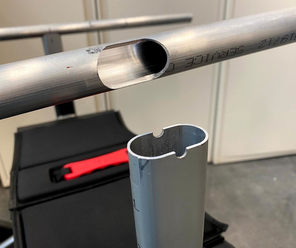
- Mill out the cross-section of the adjustment bar tubing as seen in Figure 16 (from the engineering drawing for the “Left/Right Adjustment Bar”) in the location where it meets the round handlebar tubing, seen in Figure 15 from Step 2. The result of this can be seen in Figure 17.
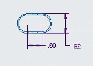
Figure 16. A close-up of the adjustment bar engineering drawing, showing the cross-section of the component. 
Figure 17. The result of milling out the cross section of the adjustment bar in the handlebar tubing - The easiest way to reconstruct this cross section is to look at it in the following fashion:
- It is constructed of two connected circles.
- Each circle has a diameter of 0.92”.
- Their centers are 0.69” apart.
- This can be seen in Figure 18.
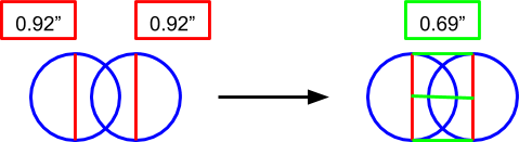
Figure 18. A visual representation of the easiest way to reconstruct the adjustment bar’s cross-section
- The easiest way to reconstruct this cross section is to look at it in the following fashion:
- Fit the handlebar tubing and adjustment bar components together (as seen in Figure 19) until the top of the adjustment bar meets the round handlebar tubing at its centerline (as seen in Figure 20), and weld along the joint.
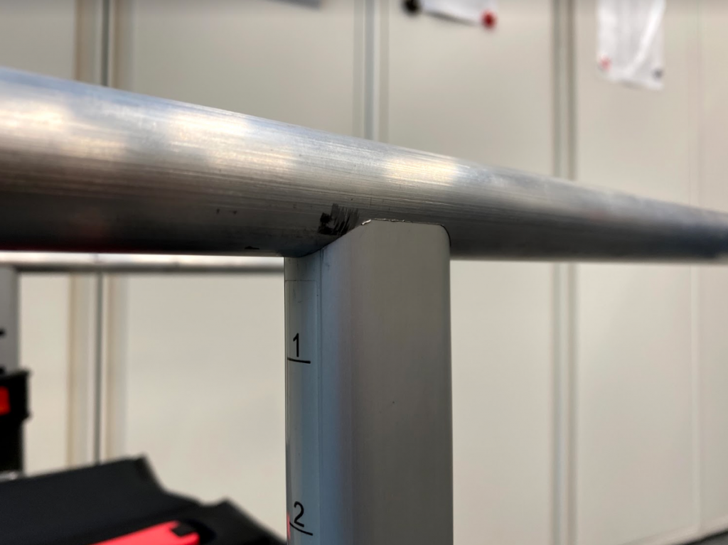
Figure 19. The adjustment bar slots into the milled out area of the handlebar tubing. 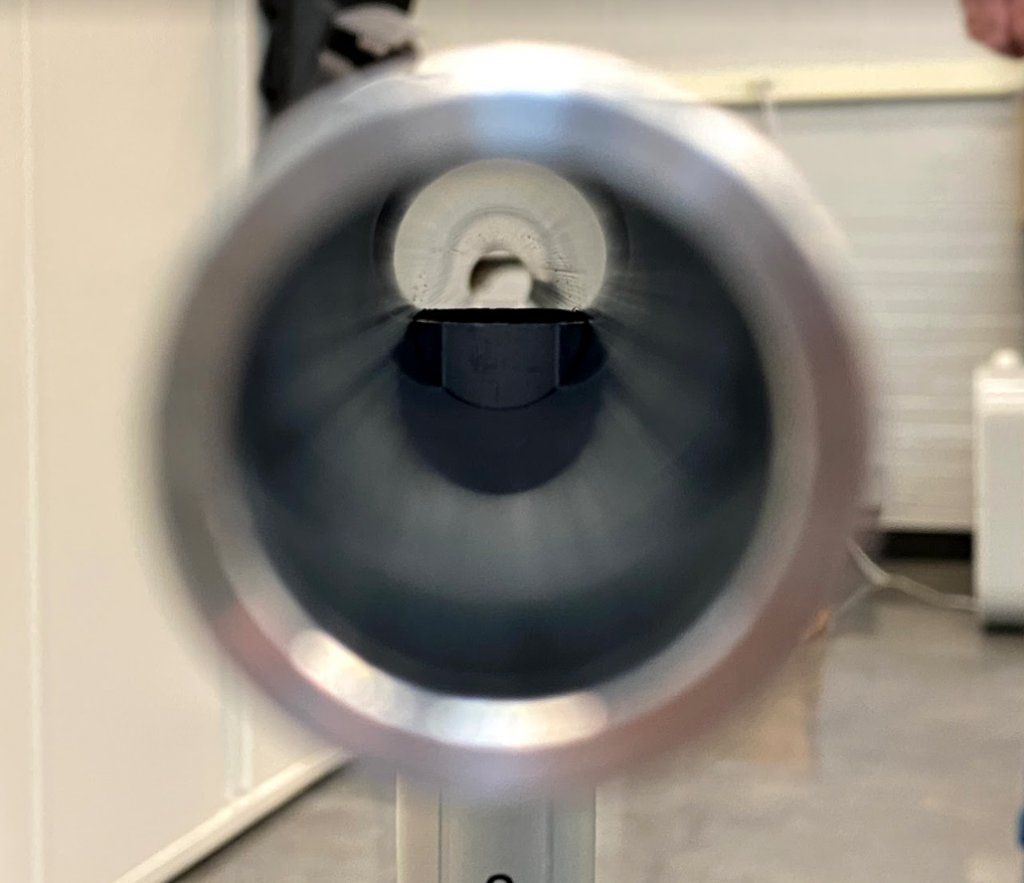
Figure 20. The adjustment bar goes through the milled out section of the handlebar tubing until it meets the tubing at its centerline before welding the joint. - Take both rubber handlebar grips and remove material starting at the open end to accommodate the adjustment bar once added onto the new handlebar system. This process is explained in the following steps.
- Trace the shape of the bottom of the adjustment bar.
- Extend the length of this trace to a length of about 3.06”, as seen in Figure 21. This 3.06” length accounts for the length from the back of the handlebar tubing to the front of the adjustment bar, as seen in Figure 22.
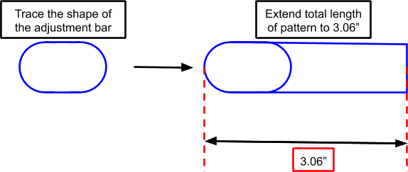
Figure 21. An illustration of the handlebar grip pattern 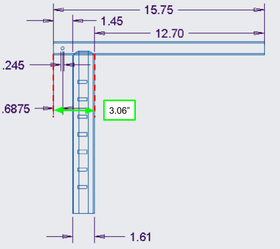
Figure 22. A close-up of the straight handlebar engineering drawing, showing where the 3.06” dimension for the pattern comes from. - Cut out this pattern and trace it onto the rubber handlebar grips, with the flat end of the pattern lining up with the open end of the grips.
- Cut out the pattern that is traced onto the rubber handlebar grips.
- Wet the whole surface of the metal handlebar tubing as well as the entire inner surface of the rubber handlebar grips with rubbing alcohol. Be extremely generous with the application of the rubbing alcohol, as it will act as the lubricant during the application process. If there is excess, that is okay, as it will evaporate over time.
- Slowly fit the rubber handlebar grips onto the handlebar tubing. This will be a tight fit, and you will need to apply a decent amount of force. Twisting side to side while pulling the rubber handlebar grips onto the tubing is fine, as long as care is taken to ensure that it has been straightened out after application. Reapply rubbing alcohol as necessary during application.
- After ensuring that the rubber handlebar grips are situated properly on the handlebar tubing, let the handlebar grips “set” by allowing the rubbing alcohol to evaporate completely before proceeding to the next step.
- Once the handlebar grips have set, cut off any excess handlebar grip material that extends past the metal tubing. Be sure not to remove any material that is supposed to cover the metal tubing.
- Mill out the backrest attachment thru-holes as seen in Figure 23 (from the engineering drawing for “Straight Left/Right Handlebar”). Mill through the BOTH the rubber handlebar grips and the metal handlebar tubing.
- The hole diameter is 0.245”.
- The center of the hole is 11/16” (0.6875”) from the back end of the handlebar tubing.

Figure 23. A close-up of the straight handlebar engineering drawing, showing the location and depth of the thru-holes for the backrest attachments.
- Use super glue (or any other high strength adhesive of your choice) to ensure that the back edges of the handlebar grips do not lift up over time. Adhesive only needs to be applied on the back length of the handlebar grip that was modified to fit the adjustment bar. Let your adhesive set and cure for the appropriate amount of time before proceeding to the next step.
- Take the existing backrest attachment and fit it to the new handlebars (as seen in Figure 24) using the sleeved bolts that previously held it to the old handlebar system.
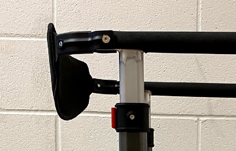
Figure 24. The orientation of the backrest attachment after final assembly with the new handlebar system - Attach the backrest to the backrest attachments using the provided nuts and screws that came with the backrest.
Constructing a set of ANGLED handlebars
The process for constructing a 10° angled set of handlebar is generally the same as for the straight set, except the intended notch position step differs from the original steps, as it will now be based on a combination of the handlebar length measurement and the handlebar height measurement that was based off of your wrist crease height. Another difference is that the angled set will have an “optimal” grip position (based on the handlebar length measurement from earlier), rather than allowing for usage throughout the length of the handle. The following instructions detail the process for constructing your own set of angled handlebars.
The same materials are required for constructing an angled set of handlebars.
- Determine your handlebar length measurement as detailed earlier.
- Determine your handlebar height measurement.
- Draw a right triangle with a 10° incline, with your known handlebar length measurement (z) set as the bottom length of the triangle, as seen in the example below in Figure 25.

Figure 25. The right triangle that needs to be set up to determine necessary notch position based on your handlebar length and height measurements. - x represents the height that the angled handlebar will rise as you move from the intended grip position to where the handlebars meet the adjustment bar.
- y represents the length of handlebar necessary for this angled design. This measurement’s significance will be explained more later.
- To solve for x, use the following equation by plugging in your own z value (where z represents the handlebar length measurement taken earlier): x = z * tan(10º)
- To solve for y, use the following equation by plugging in your own z value (where z represents the handlebar length measurement taken earlier): y = z/cos(10º)
- After solving for x, you will now be able to determine which notch position is necessary for this design, as x represents the height increase from your intended grip position if set your wrist crease height.
- The adjustment bar itself will also be cut at a 10° angle, so there will be height differences that result from that angled cut at each end (as seen in Figure 26), which is 0.1415”. This will allow you to determine the maximum height necessary for your adjustment bar notch position, as you will know the total height necessary for your angled handlebar design. This value can be found by adding the value calculated for x in the last step, the handlebar height measurement taken earlier, and 0.1415”.
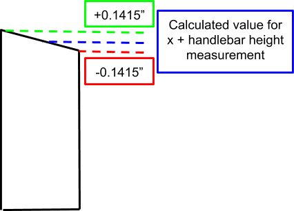
Figure 26. An illustration of the angled cut to the adjustment bar, and the resulting height differences at each end. - Once you know the total height, proceed with choosing an appropriate notch position for the adjustment bar as detailed in the straight handlebar position as detailed in Step 1 in the straight handlebar instructions.
- After solving for y, you will be able to determine how to modify the existing dimensions of the engineering drawings for your own angled handlebar set. This process will closely follow the same process used for the straight handlebar set.
- The dimensions that will be modified are the 12.81” dimension and the 16.00” dimension, seen in Figure 27 below (from the engineering drawing for the “Angled Left/Right Handlebar”). This figure represents a handlebar with a horizontal length of 13.50” from the vertical centerline of the adjustment bar, set at 10° angle. The 12.81” measurement represents the resulting length from this angle, measured from the side of the adjustment bar, as this way of dimensioning the measurement is more useful for fabrication than a dimension represented from an imaginary centerline. For the purposes of comparison to the calculated y value, the distance relative to the centerline was also added.
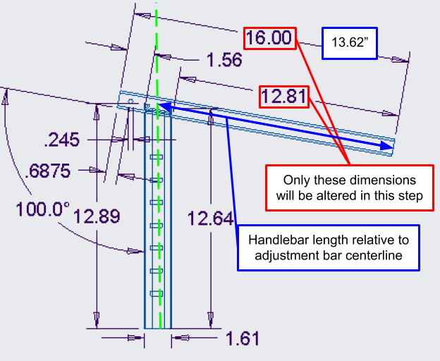
Figure 27. A close-up of the angled handlebar engineering drawing, showing the handlebar length dimensions that will be altered. - Depending on how long your calculated y value compares to the 13.62” dimension (length of the handlebars relative to the adjustment bar centerline), you will modify the 12.81” and 16.00” dimensions accordingly.
- If your calculated y value is 9.62”, then it is 4” shorter than the 13.62” dimension from the original design. Therefore you will subtract 4” from the 12.81” and 16.00” dimensions, and your new altered values for those dimensions will be 8.81” and 12.00” respectively.
- The dimensions that will be modified are the 12.81” dimension and the 16.00” dimension, seen in Figure 27 below (from the engineering drawing for the “Angled Left/Right Handlebar”). This figure represents a handlebar with a horizontal length of 13.50” from the vertical centerline of the adjustment bar, set at 10° angle. The 12.81” measurement represents the resulting length from this angle, measured from the side of the adjustment bar, as this way of dimensioning the measurement is more useful for fabrication than a dimension represented from an imaginary centerline. For the purposes of comparison to the calculated y value, the distance relative to the centerline was also added.
- As explained in Step 5, the adjustment bar itself will also be cut at a 10° angle. The way that the adjustment bar will be cut will be based on the value for x that was calculated earlier and the handlebar height measurement. Refer to Figure 28 and Figure 29.

Figure 28. A close-up of the adjustment bar engineering drawing, showing the original height of the component before modification. 
Figure 29. A close-up of the angled handlebar engineering drawing, showing the modified height of the adjustment bar due to the angled cut. - As seen in Figure 28, the original height of the adjustment bar component is 13.07”. Just as for the straight handlebar set, the component will need to cut down, and this time will also need to be done at a 10° angle. This process is simplified by the 12.89” and the 12.64” dimensions seen in Figure 29.
- These two dimensions represent the heights where the cut will start and end, i.e. start the cut at 12.64” from the bottom of the adjustment bar and end the cut at 12.89” from the bottom and you will end up with a properly angled cut for the angled handlebar set.
- These dimensions will need to be replaced based on your calculated x value, your handlebar height measurement, and the intended notch position that was determined earlier.
- First, set the adjustment bar in the necessary notch position for the angled handlebar set that was determined in Step 6.
- Measure the height from the ground to the top of the adjustment bar in this position.
- From this measurement, subtract the value of x and the handlebar height measurement.
- Take the value calculated in Step iii, and subtract it from 13.07”. From this point you will have a value that we will refer to as “U”.
- From here, you can replace the 12.89” and 12.64” dimensions using the known height difference from U.
- This height difference (0.1415”) from U was calculated based on the known angle of 10° and the known width of the adjustment bar component.
- The 12.89” dimension will be replaced by your calculated U value plus 0.1415”.
- The 12.64” dimension will be replaced by your calculated U value minus 0.1415”.
- Once those dimensions have been replaced, you will be able to know where the angled cut for the adjustment will start and stop along its height and can proceed with modification of the component.
- A similar process to the one detailed in Steps 3 – 4 of the straight handlebar instructions will be followed to mill out the cross section of the adjustment bar, with one key difference. This time it will be milled at 100° angle to the handlebar, rather than completely perpendicular to the surface. This will be milled out in the location indicated in Figure 30, indicated by the 1.56” dimension and the 12.81” dimension that was altered in a previous step. If modifying the original plans, ensure that you use the modified replacement dimension determined earlier, rather than the original 12.81” dimension.
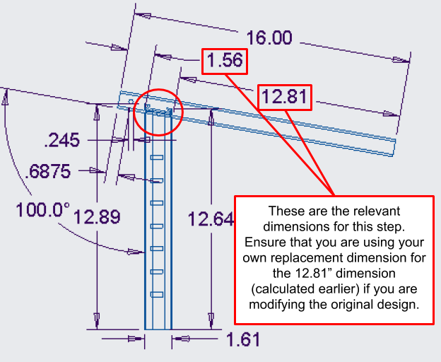
Figure 30. A close-up of the angled handlebar engineering drawing, showing the location where the adjustment bar’s cross-section will be milled out at a 100° angle on the handlebar tubing. - After the hole for the adjustment bar has been milled, fit the modified adjustment bar and the handlebar tubing together until they meet at the centerline of the round tubing (as shown in Step 4 of the straight handlebar instructions), and then weld along the joint.
- To modify the rubber handlebar grips to fit over the angled handlebar set, the exact same process detailed in Step 5 of the straight handlebar instructions will be followed, except that the overall length of the pattern should now be 3.20” rather than 3.06”.
- The same process detailed in Steps 6 – 9 of the straight handlebar instructions will be followed for the remaining steps of the rubber handlebar grip application process.
- The same process detailed in Step 10 of the straight handlebar instructions will be followed to mill out the backrest attachment thru-holes.
- The same process detailed in Step 11 of the straight handlebar instructions will be followed to adhere the back portion of the handlebar grips, again using a strong adhesive of your own choice.
- The same process detailed in Steps 12 – 13 of the straight handlebar instructions will be followed to attach the backrest attachments and the backrest itself to the new angled handlebar set.
Construct the bottom frame extension
- Purchase required parts (1” square aluminum block, extra body frame)
- Take out the wheel assemblies from the existing body frame
- Punch holes through the existing body frame (Figure 31)
- Punch holes through the square aluminum block (Figure 32)
- Punch holes and the notch through the extension frame (Figure 33)
- Fasten the existing body frame and square aluminum block with 0.245” screws and nuts
- Fasten the extension frame onto the assembly with screws and nuts
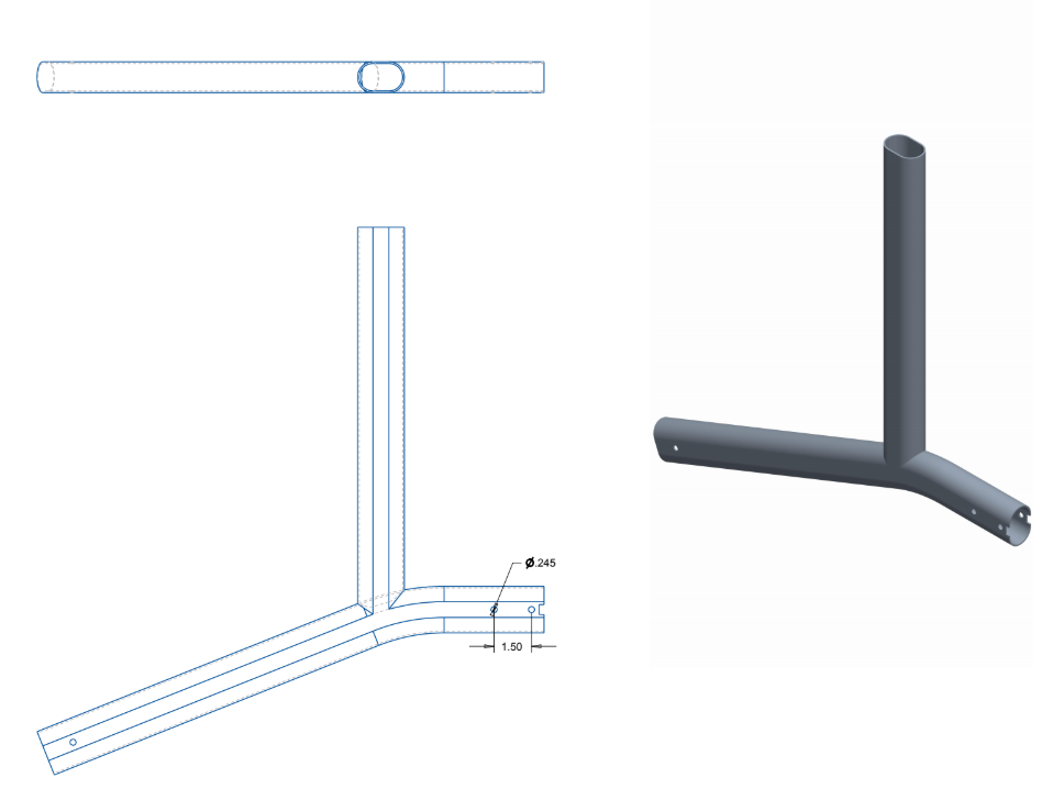
Figure 31. Existing body frame engineering drawing. 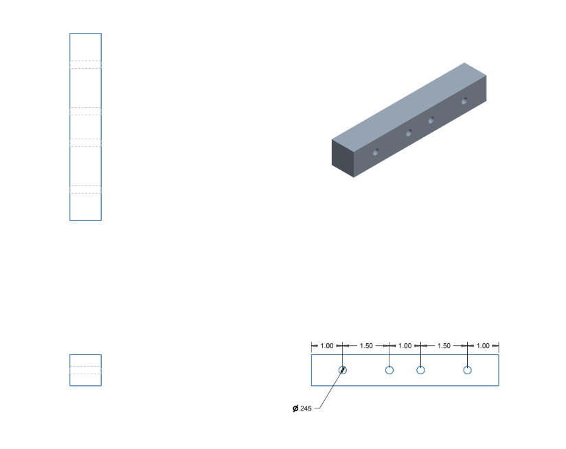
Figure 32. Square aluminum block engineering drawing. 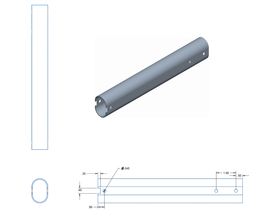
Figure 33. Extension frame engineering drawing.
Wheels
The wheels of the J-Walk can be modified to either use the original Triumph Escape’s wheels (which point straight outwards), or the Lifestyle 950 Commando’s wheels (which flare out). The advantage of the flared out wheels over the straight wheels is that it provides more walking room near the end of the frame, if necessary.
If you do not feel like you need the extra walking space, feel free to skip this step, but if you need the space, the steps to install the flared out wheels are relatively simple after you have purchased the flared out set of wheels.
- Unscrew and remove the nuts and bolts that hold the existing wheels in (which were most likely already removed before the frame extension).
- Pull out the existing straight set of wheels (this may take a little bit of force).
- Install the new flared out set of wheels.
- Reinstall the nuts and bolts into the holes.
Add cushioning to crossbeams
During the initial testing phase of the original J-Walk gait trainer, the client found that the back of her legs would often collide with the crossbeams of the gait trainer if she held the handlebars too close to the seat. The team provided foam cushioning at the contact point on the crossbeams in order to alleviate this issue. After further testing, this issue mostly went away, as the client just had to adjust to usage of the J-Walk in comparison to her original gait trainer. However, instructions on how to apply your own crossbeam cushions can be found below if necessary.
The following materials will be required to fabricate the new handlebar system. More details can be found on where to purchase these items in the Bill of Materials.
- Foam edge protectors
- A strong adhesive of your choice (super glue, epoxy)
Once the necessary materials have been procured, these simple instructions will allow you to install the crossbeam cushions.
- Take the roll of foam edge protector and cut two (2) 5 inch long sections.
- Using the provided adhesive, place the foam edge protectors in the desired position on the plastic crossbeam member, seen in Figure 34.
- Using a strong adhesive of your choice, permanently adhere the foam edge protectors to the plastic crossbeam member.
- Let the adhesive set for the appropriate amount of time, as per the instructions on the packaging.
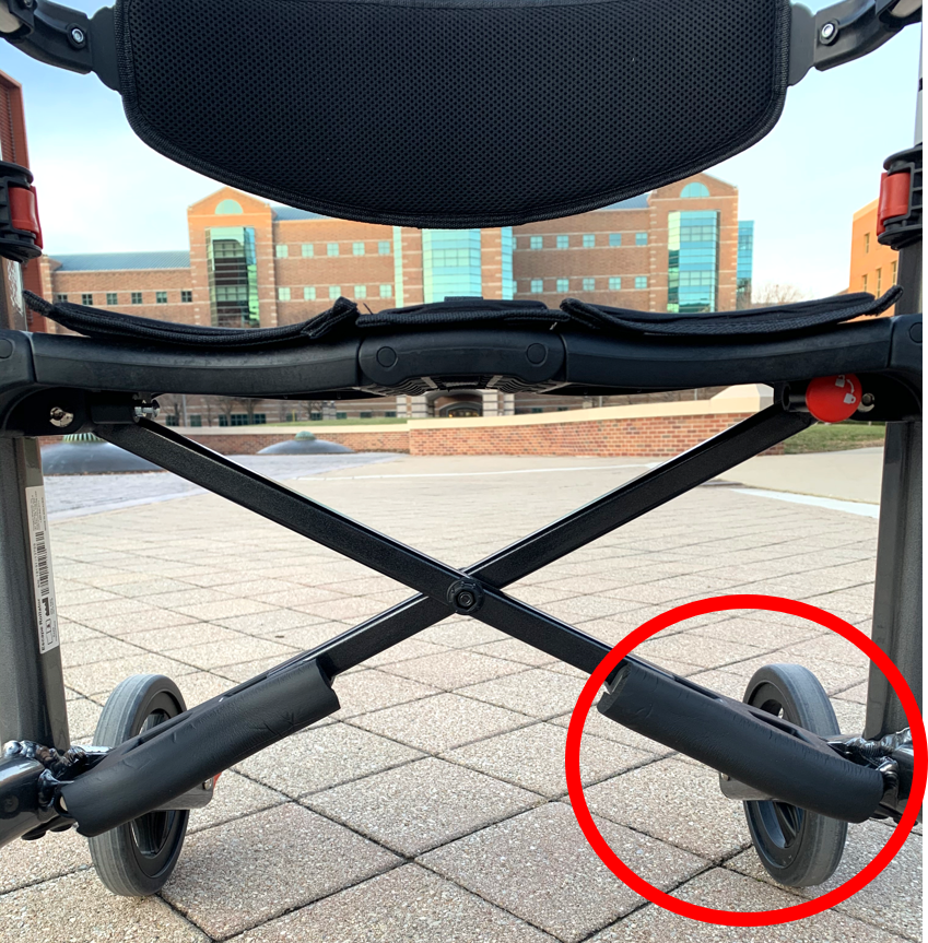
Figure 34. The foam cushioning applied to the plastic crossbeam members.
References
[1] Lee, S.Y., Kim, S.C., Lee, Y.I., 2017, “Effect of a Modified Grip Angle of a Walker On the Wrist Deviation Angle, Muscle Activation and Palmar Load During Walker-Assisted Gait in Elderly People”, Journal of Physical Therapy Science, 29(3), pp. 405-408
[2] Bradley, S. M., Hernandez, C.R., 2011, “Geriatric Assistive Devices”, American Family Physician, 84(4), pp. 405-411