Exoskeleton Test Bed | Upper-body Mannequin | Pneumatic Controller | Downloads
The upper-body mannequin is comprised of 3 sub-assemblies
- Torso
- Shoulder Joint
- Arm
The fabrication guidelines for building your own upper-body mannequin are presented below. We suggest reading the Bill of Materials available under the Downloads tab before proceeding. All the design files are also available under the Downloads tab.
Torso
The torso is a stack of plywood sheets which are held in position by a T-stand, spacers and threaded rods. The topmost piece of torso (collar) is 3D printed.
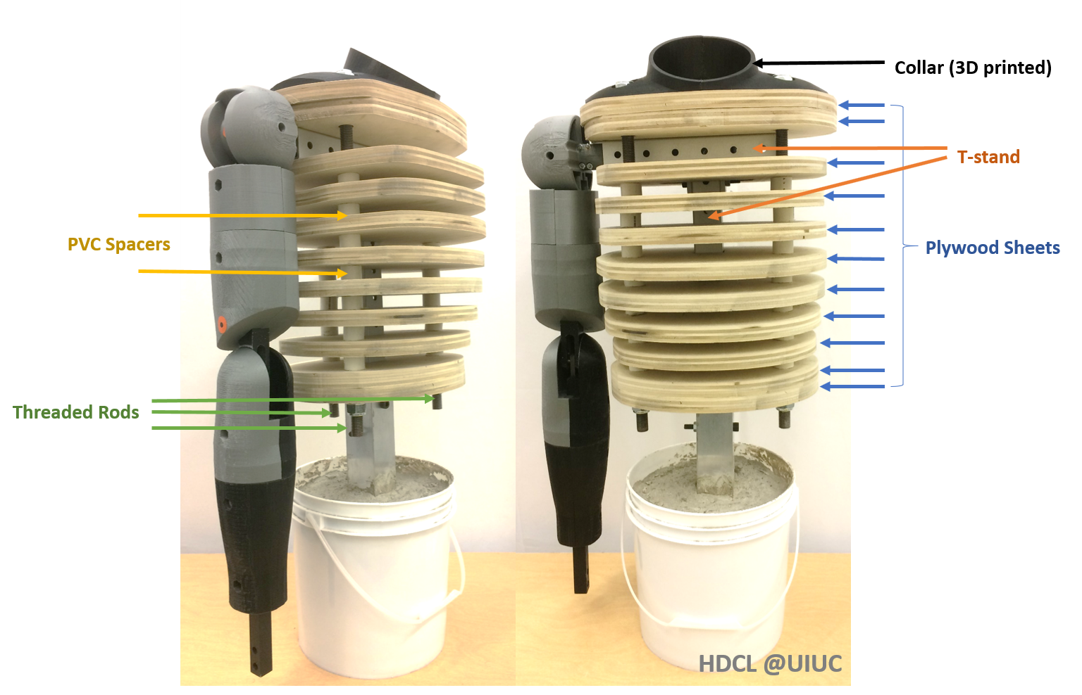
Figure 1: Components comprising the Torso sub-assembly
Prepare Parts/ Sub-assemblies for Torso
- T-stand:
Use the 1 ½“ Aluminum bolt-together framing to create a T-stand to align and support the stack of plywood sheets.
Cut the 2 ft aluminum framing to get 2 pieces – one 250 mm long and other 370 mm long.
Bolt them together in a T-arrangement using corner brackets such that the blue dimension in figure 2 is nearly or a little larger than 100 mm.
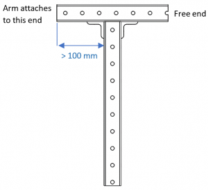
- Figure 2: T-stand
- Plywood Sheets:
We provide the cross-sections of torso at different heights along the vertical as drawings. Use these drawings to cut 3/4“ thick plywood sheets. We used a water-jet cutter to create the sections.
These sheets will be stacked up to create the shape of torso. - PVC Spacers:
Cut the PVC pipe into 21 3/4“ long segments. These segments act as spacers between plywood sheets. - Threaded Rods:
Cut the threaded rod to get 3 pieces at least 430 mm long each. - Collar Region:
3D print the 4 parts of the collar region. Join the 4 pieces using friction welding or any other convenient method.
Assemble Torso
- Screw the lock nuts on one end of the threaded rods. Pass these rods through the holes in the connected collar region such that the nuts emerge at the top end of the torso.
- Stack the topmost 2 plywood sheets below the collar part by passing the threaded rods through their respective holes.
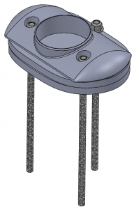
Figure 3: Four 3D printed parts welded together to make the collar
Threaded rods passed through holes in the collar and top 2 sheets
- The T-stand is placed next. The T-stand passes through the rectangular hole in the remaining lower sheets.
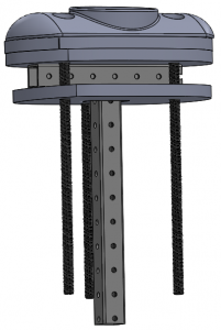
Figure 4: T-stand placed below collar and top 2 sheets
Third sheet (and all below it) have a rectangular hole for T-stand
- Keep stacking the plywood sheets in their order while passing the rods through corresponding holes and putting PVC spacers between the sheets.
See figure 5 and note that the bottom 2 sheets do not have any spacers between them. The rods must go through the spacers to restrict the spacers from moving. - Screw the lock nuts at the bottom end after stacking all the plywood sheets.
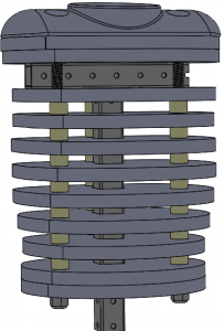
Figure 5: Assembled torso
Shoulder Joint
- 3D print 4 parts (filenames – partholderNut_shoulder, partholderHead_shoulder, partinsertLeft, partinsertRight).
- Cut 3/8” diameter D-rod to get 120 mm long segment. Place the collar brackets and bearings at locations shown in figure 6. Insert D-rod and secure with collar brackets.
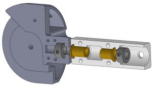
Figure 6: Locations of collar brackets (dark grey) and
sleeve bearings (golden) in sub-assembly
- Connect the two halves together using screws ensuring free rotation of grey part (partholderNut_shoulder + partholderHead_shoulder) w.r.t white part (partinsertLeft + partinsertRight)
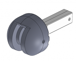
Figure 7: Assembled shoulder joint
Arm – Upper and Lower Arm
- Mill and drill the metal bars using the given drawings.
- 3D print the 8 parts of shell (outer surface) of the arm. Four parts each for upper and lower arm as shown in figure 8. The lower arm shells are different colors because we ran out of grey color filament.

Figure 8: Arm shell is made of 8 parts
- Join the 2 bars at the elbow joint using a pin joint as shown in figure 9. The hole in inner flange (part of lower arm) is sufficiently big to allow modest rotation to mimic some supination-pronation of the lower arm.
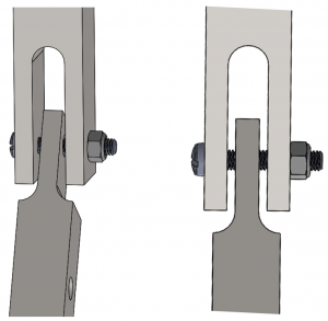
Figure 9: Elbow joint connecting upper (light grey) and lower arm (dark grey) metal bars
- Fix the 3D printed plastic parts to the metal bar using screws/ nuts. Then use friction welding to connect 3D printed parts together.
Overall Assembly
- First, insert the shoulder sub-assembly inside the horizontal section of the T-stand. Align the hole highlighted with a red circle in figure 10 with any of the holes on the T-stand.
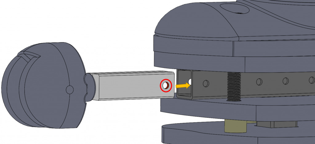
Figure 10: Assembling shoulder and torso
- Insert the upper arm metal bar in the slot of shoulder joint and form a pin joint connecting the entire arm to the shoulder (figure 11). Use a metal unthreaded pin to create a pin joint to ensure smooth operation. The dimension of the holes in the 3D printed shoulder joint result in a press-fit connection with the unthreaded pin.
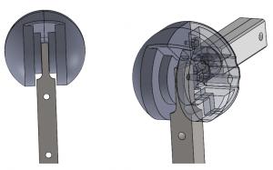
Figure 11: Upper arm metal bar connected to shoulder through a pin joint
- Your assembled mannequin would look like the figure below.
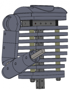
Figure 12: Fully assembled upper body mannequin